It's taken quite a long time to get the most critical part of the exhaust system fabricated. There's just barely room for the necessary piping so precision was critical. Finally all the exhaust that connects from the exhaust ports to the turbo inlet is done. Exhaust crosses over from the right side to the left and then runs forward to the turbo in front of the engine. Here it is assembled on the floor.
It's welded out of 1/8" thick stainless steel tube with v-band connections to ease installation and flex couplings to avoid cracking from heat stresses.
I used up a lot of time and stainless steel tube making parts that weren't quite good enough. The first attempt at the manifolds warped so much during welding that I just had to scrap them and start over. I learned a lot about welding stainless though so it wasn't a complete loss. The next step is to wrap it up with exhaust wrap and then it can be bolted up.
Monday, April 9, 2012
Turbo placement
Before I can get much of the exhaust fabrication done the turbo location has to be determined.
Moving the radiator down and forward left just enough space for the turbo to sit right in front of the motor.
It's a pretty tight squeeze with only about 3/4" clearance from the power steering pump, upper control arm and top of radiator but it will be fine. This is not the crappy original GM-1 turbo. After many hours of research I settled on a Holset WH1C. This turbo was used on early Dodge Cummins pickups.
It's supported with a bracket attached to the front crossmember.
Moving the radiator down and forward left just enough space for the turbo to sit right in front of the motor.
It's a pretty tight squeeze with only about 3/4" clearance from the power steering pump, upper control arm and top of radiator but it will be fine. This is not the crappy original GM-1 turbo. After many hours of research I settled on a Holset WH1C. This turbo was used on early Dodge Cummins pickups.
It's supported with a bracket attached to the front crossmember.
Monday, January 16, 2012
Turbo exhaust fabrication
Now that the radiator and transmission are in place I can finally get started on what I think will be the most challenging part of the project - fabrication of the exhaust system for the turbocharger. There's not very much room for all the piping so things will have to be fitted just right.
My first step will be building a couple of exhaust manifolds. The stock 6.5L manifolds won't fit. I looked at the Humvee headers and thougth I could use them but nope, not a chance. So here I go making my own manifolds. First I had Metal Products Company ( my neighbors) laser cut some flange plates to bolt the manifold to the head.
I wanted to just make one long plate with the appropriate holes in it for the exhaust ports and bolt holes. Unfortunately, unlike other motors I've seen the exhaust side of the 6.5 head is not one machined flat surface. Instead, there is a separate machined surface around each exhaust port with raised raw casting in between. That means making separate flange plates for each port.
I found some 1-1/4" stainless steel weld up schedule 10 pipe elbows. These are just the right size to make the bends coming out of the port flanges. In the hydraulic press I mashed one end of the elbow into a rectangle shape to fit into the exhaust flange. Here it is tack welded in place.
Once I had the size and shape figured out I made a tool to 'square' the ends of the elbows using the hydraulic press.
The new manifold has to be very compact. Once all the elbows were formed, fitted and welded I made a fixture to cut them all off at the same angle in preparation for welding to a 'log'.
My first step will be building a couple of exhaust manifolds. The stock 6.5L manifolds won't fit. I looked at the Humvee headers and thougth I could use them but nope, not a chance. So here I go making my own manifolds. First I had Metal Products Company ( my neighbors) laser cut some flange plates to bolt the manifold to the head.
| Laser cut steel flanges. I had Metal Products make 20 of them so I would have plenty to ruin while I figured out how to build the manifold. |
I wanted to just make one long plate with the appropriate holes in it for the exhaust ports and bolt holes. Unfortunately, unlike other motors I've seen the exhaust side of the 6.5 head is not one machined flat surface. Instead, there is a separate machined surface around each exhaust port with raised raw casting in between. That means making separate flange plates for each port.
I found some 1-1/4" stainless steel weld up schedule 10 pipe elbows. These are just the right size to make the bends coming out of the port flanges. In the hydraulic press I mashed one end of the elbow into a rectangle shape to fit into the exhaust flange. Here it is tack welded in place.
| One passenger side exhaust elbow |
The new manifold has to be very compact. Once all the elbows were formed, fitted and welded I made a fixture to cut them all off at the same angle in preparation for welding to a 'log'.
| Four drivers side exhaust elbows |
Transmission test fit
I finally found a 2nd generation 4L60E. It's longer than the TH350 that came out of the car so something had to be done with the tranny mount. On the Corvette the transmission mount bolts to a removable crossmember that spans across the frame rails. I considered modifying the stock crossmember but I found an aftermarket crossmember at Bow Tie Overdrives that bolted right up with no mods and has the benefit of increased clearance for the exhaust.
The trans is just temporarily bolted in place. I need it there to start working on fabricating the exhaust. I'll have to order up an appropriate torque converter, and probably modify the dipstick tube before it can be bolted in permanently. The Bow Tie crossmember will also need to go out for powdercoating. I ordered it in raw steel because I wasn't certain I would not have to make some modifications. Grinding off powdercoat to make welded modifications is a big pain.
| There's the 4L60E bolted right up to the 6.5 |
| Bow Tie Overdrives crossmember. It's intended for the LS1 motor swap but works perfectly here. |
Radiator & coolant hoses
I've been making good progress but it takes a while to get to the point of having something to show. The radiator is in. I ended up cutting off the bottom half of the stock radiator support and moving the radiator as far down and forward as possible. This will give me more room in front of the motor which is where the turbo has to live. With the radiator mostly out of the way running the turbo plumbing will be much simpler.
The coolant plumbing is made up of silicone elbows and aluminum tube. The straight pieces of tube need a lip formed on the end to help prevent the hose blowing off under pressure. I made a quick & dirty tool to crimp the hose bead into the tube ends. Check it out.

The disk pushes tube lip into the 'V' groove.
Make a crimp, rotate the tube a little and repeat.
| Here's a view of the radiator from underneath |
| View from the top. The radiator sits about a foot lower than original. |
The coolant plumbing is made up of silicone elbows and aluminum tube. The straight pieces of tube need a lip formed on the end to help prevent the hose blowing off under pressure. I made a quick & dirty tool to crimp the hose bead into the tube ends. Check it out.

The disk pushes tube lip into the 'V' groove.
Make a crimp, rotate the tube a little and repeat.
Wednesday, December 14, 2011
Alternator, serpentine belt and tensioner
So... Now that the motor is in the car there are all kinds of challenges to be addressed. Exhaust routing is going to be the biggest one. I'm still working that out and gathering materials to tackle that job soon.
I figured the best place to start sorting things out was getting the hood to close and getting all the engine driven accessories (A/C compressor, power steering, alternator, etc.) installed. The original GMC mounting of the alternator resented a problem. The alternator was about an inch too high to allow the hood to close. After considering a couple of options for relocating it I realized I could just rotate the alternator down on its main mount by modifying the alternator support bracket.
Moving the alternator meant screwing up the geometry of the serpentine belt tensioner. I made a relocation bracket to rotate the tensioner over and down to get it in the same position relative to the alternator as it was before.
Success! The tensioner works correctly and the original length belt still fits...
But just barely! Down at the power steering pump there's only about 1/8" clearance between the belt and the upper control arm pivot shaft. Not much, but it's enough!
The finished bracket with power steering pump reservoir.
I figured the best place to start sorting things out was getting the hood to close and getting all the engine driven accessories (A/C compressor, power steering, alternator, etc.) installed. The original GMC mounting of the alternator resented a problem. The alternator was about an inch too high to allow the hood to close. After considering a couple of options for relocating it I realized I could just rotate the alternator down on its main mount by modifying the alternator support bracket.
![]() |
| Original alternator mount |
![]() |
| Lower mount |
Moving the alternator meant screwing up the geometry of the serpentine belt tensioner. I made a relocation bracket to rotate the tensioner over and down to get it in the same position relative to the alternator as it was before.
Success! The tensioner works correctly and the original length belt still fits...
But just barely! Down at the power steering pump there's only about 1/8" clearance between the belt and the upper control arm pivot shaft. Not much, but it's enough!
The finished bracket with power steering pump reservoir.
Thursday, December 8, 2011
Is it in yet...?
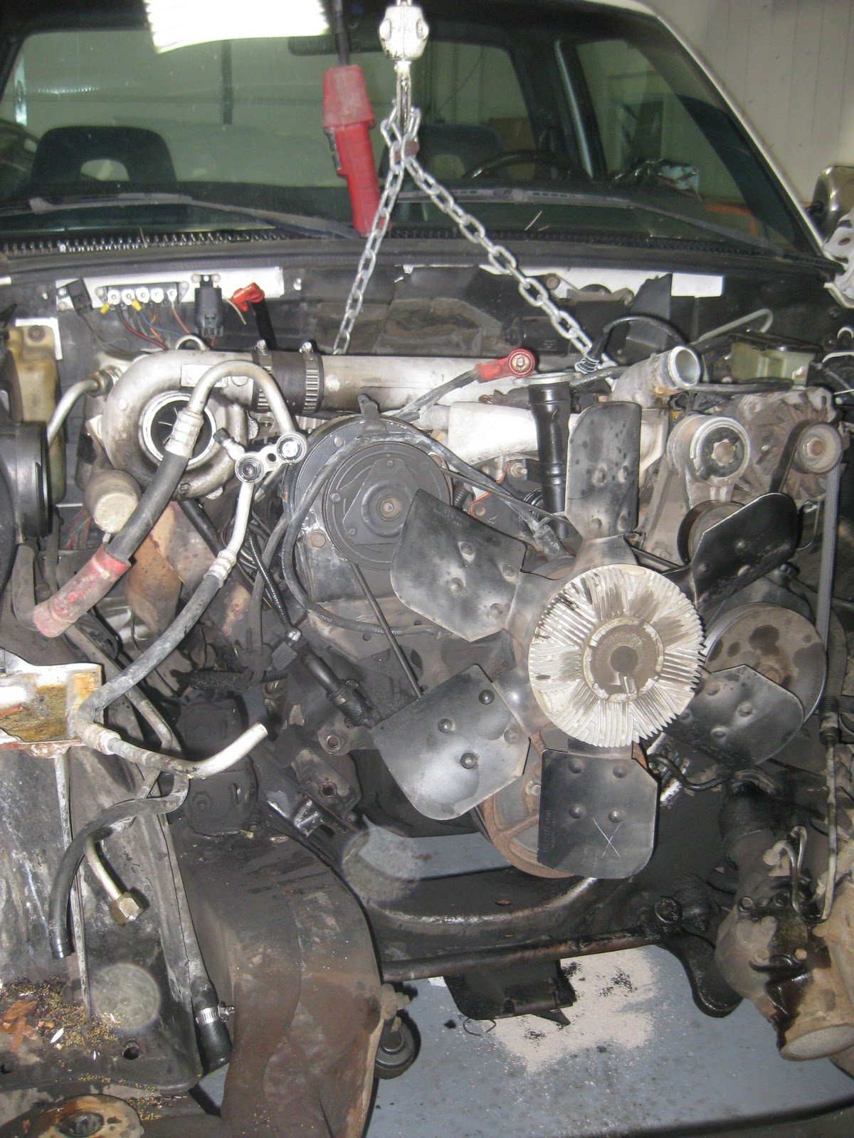
It's good to have the 6.5 off the engine stand and into the car. Yes, it's a tight fit! I figure at this point I've done almost all of the easy stuff - pulling motors, taking things apart, fooling with the motor on the stand. Now the real work begins.
Sunday, December 4, 2011
Frame modification
Making individual bends is much easier than trying to form a smoothly curved piece. You can sharpen or flatten each bend until it matches up just right.
Saturday, December 3, 2011
Wednesday, November 30, 2011
Sunday, November 27, 2011
Out with the old (350)
![]() |
| The 350 L48 motor comes out |
![]() |
| A piece of channel is bolted to the frame rails and runs under the transmission. |
I made a simple brace to hold the TH350 transmission in place while the 6.5 gets fitted to its new home.
Pulley clearance
The 6.5 diesel is almost 2.5" longer than the small block 350. This means the front pulley is going to end up over the crossmember rather than just behind it. One solution would be to cut a piece out of the crossmember and weld in a patch with more clearance.Another solution would be to make spacer plates to raise the motor up at the motor mounts. Raising the motor would also give a little additional ground clearance.
The downside to raising the motor will be decreased clearance under the hood and decreased clearance between the bellhousing and firewall.
Here's a drawing for a motor mount spacer plate. Because it will sit at a 45 degree angle a 5/8" thick plate will raise the motor about 7/8".
I'll probably make both modifications. If raising the motor runs into too many unseen difficulties I can remove the spacer plates. If I've already modified the crossmember I won't have to pull the motor back out to do it later.
Thursday, November 24, 2011
Which transmission?
Certainly not the TH350 that is in the Corvette now. To keep the diesel motor happy at freeway speeds it will need something with an overdrive. The GMC pickup has a 4L80E which is a very robust transmission. It's also quite a bit larger and longer than what's in the Vette right now. It would probably be possible to stuff the 4L80E into the tunnel but that looks like a really tight fit and a lot of trouble. Plus, I would probably lose about an inch of precious ground clearance.
The 700R4 would be a good choice. It has a nice low first gear for good off the line response and a nice tall overdrive for relaxed freeway cruising and good fuel economy. Then there's the 4L60E which is a computer controlled version of the 700R4. I would have to use a stand alone aftermarket controller which complicates the installation a little bit and adds to the expense. One nice advantage to the 4L60E with aftermarket controller is all the shift parameters can be dialed in without digging in to the valve body. The controller will also support the use of paddle shifters. I would like that a lot.
For the time being I can get a lot done without having the actual transmission I'm going to use. I'll leave the TH350 in there for now and bolt the 6.5 to it (no torque converter or flex plate). That will give me an accurate motor position and I can work on plumbing for the turbo, modifications to the thermostat housing, wiring, fuel supply, etc.
The 700R4 would be a good choice. It has a nice low first gear for good off the line response and a nice tall overdrive for relaxed freeway cruising and good fuel economy. Then there's the 4L60E which is a computer controlled version of the 700R4. I would have to use a stand alone aftermarket controller which complicates the installation a little bit and adds to the expense. One nice advantage to the 4L60E with aftermarket controller is all the shift parameters can be dialed in without digging in to the valve body. The controller will also support the use of paddle shifters. I would like that a lot.
For the time being I can get a lot done without having the actual transmission I'm going to use. I'll leave the TH350 in there for now and bolt the 6.5 to it (no torque converter or flex plate). That will give me an accurate motor position and I can work on plumbing for the turbo, modifications to the thermostat housing, wiring, fuel supply, etc.
Almost time to get the motor out of the Vette
There's a bit more to do to the 6.5 before it's ready to be dropped into its new home under the Corvettes hood. Even so, it getting to be time to get the 350 gasser pulled out. There will be plenty of tidying up to do in the Vette engine bay.
The view under the Vette hood. Ughh... The first thing to do will be to remove the radiator shroud and intake snorkels so I can get in deeper with a tape measure. I want to keep the car drivable for a little while longer.
Tuesday, November 22, 2011
The 6.5 looks a little better now
It is not a thing of beauty but at least it's presentable. The top half of the intake manifold is a snorkel that connects to the turbocharger that will be mounted to the right hand side of the motor. I'm going to have to modify all the turbo plumbing to get the turbo to fit in the tight space under the Corvette hood. That top snorkel will have to either be modified or (more likely) replaced with a fabricated part. The same goes for the water outlet and thermostat housing. It looks like it is going to be a little bit too tall. I'll probably have to make a replacement that doesn't stick up so high.
More motor prep
I figure the Diesel Corvette is going to be a bit of a curiosity. Folks are going to want to look under the hood to see that big ugly diesel lurking in there. That means it needs to be made presentable. The oil pan is already looking pretty so I figure I better pull the valve covers and intake manifold and give them a good cleaning and a coat of paint.
To get the valve covers off you have to remove the fuel injection lines. The get the injection lines off you have to pull the intake manifold. Here's pics of the injection lines. The lines have to come off in the right order or you can't get a wrench in where you need to. The same goes for putting it back together.Check out the cobbled up (rubber) fuel supply lines. That will get tidied up as well.
![]() |
Shortening the oil pan
One thing I knew from the start was the 6.5 oil pan was going to have to be modified. The diesel holds a lot more oil than the gas motor and the oil pan is a lot deeper. The Corvette doesn't have much ground clearance to start with so the oil pan has to be shortened.
I measured how far the oil pump protruded down into the pan and marked a cut line around the sump. Off to the bandsaw! There's a little bit of a thrill to be had taking perfectly good expensive parts and running them through a saw. Now you're committed! It worked out fine. I cut a piece of diamond plate to fit the oil pan bottom and welded it in place. I made it about 1/8" too short so a quick trip to the hydraulic press put a dimple in it right below the oil pump body for clearance. The pan is now about 1 1/2" shorter than stock. With this modification and some mods to the motor mounts to carry the motor a little higher I should have about the same ground clearance as 350 gas motor.
More reference pictures with the motor on the stand:

I measured how far the oil pump protruded down into the pan and marked a cut line around the sump. Off to the bandsaw! There's a little bit of a thrill to be had taking perfectly good expensive parts and running them through a saw. Now you're committed! It worked out fine. I cut a piece of diamond plate to fit the oil pan bottom and welded it in place. I made it about 1/8" too short so a quick trip to the hydraulic press put a dimple in it right below the oil pump body for clearance. The pan is now about 1 1/2" shorter than stock. With this modification and some mods to the motor mounts to carry the motor a little higher I should have about the same ground clearance as 350 gas motor.
More reference pictures with the motor on the stand:

Pulling the diesel motor

During the motor-ectomy I tried to take a bunch of reference photos. I probably should have taken more. Photos are really helpful when you're looking at some parts and trying to remember how they fit together.
![]() |
| Hydro-boost hoses |
![]() |
| waste gate actuator |
![]() |
| Battery positive bus bar |


![]() |
| WTF! There's no crank position sensor. This motor doesn't need one but the hole should be plugged. |
Subscribe to:
Posts (Atom)